Domain Setup
Note
For simplicity, we omit the \(z\) direction on this page. Practically, it is treated in the same manner as the \(y\) direction.
Staggered Grid and Domain Decomposition
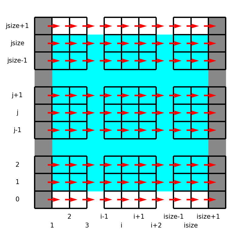
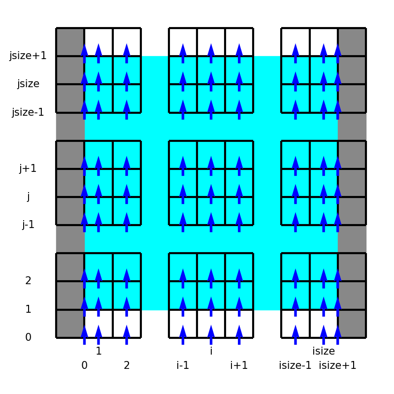
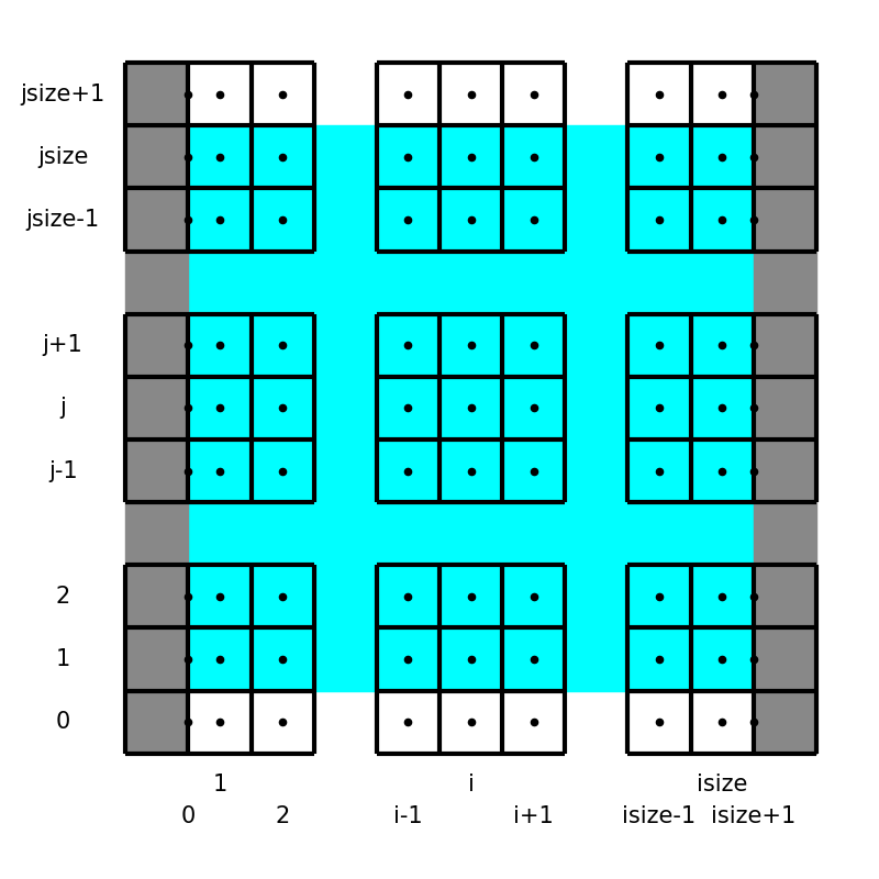
In this project, we utilize the staggered grid arrangement, i.e., all velocity components, pressure, and temperature are defined at different locations:
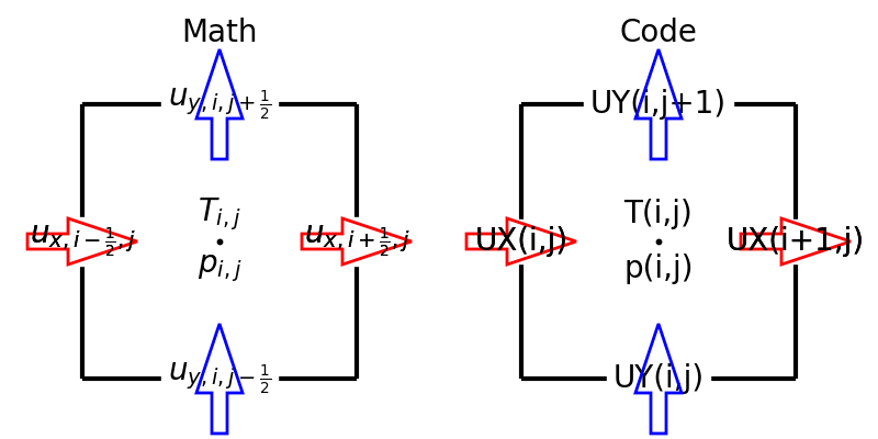
Here the left panel shows the locations and indices of the variables in the equations, while the right schematic describes notations used in the code.
We assume that the domain is wall-bounded in the \(x\) direction, while periodic boundary conditions are imposed in the other directions.
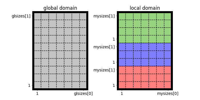
The spatial resolution denotes the number of cell centers (where pressure and temperature are defined): e.g., glisize = domain->glsizes[0] and gljsize = domain->glsizes[1] in the \(x\) and \(y\) directions, respectively.
Note that the prefix gl is used to emphasize they are global.
This library supports process parallelization (in particular by means of Message Passing Interface: MPI), splitting the whole domain into smaller blocks, and each process is only responsible for myisize x myjsize = domain->mysizes[0] x domain->mysizes[1] cell centers:
Note
No decomposition in the wall-normal direction
In this project, the wall-normal direction is not decomposed, and we adopt the so-called pencil decomposition. Thus
glisize = glsizes[0]andmyisize = mysizes[0]are equal.Pencil sizes can be different
Although domains are decomposed such that each process has a similar workload,
myjsizecan be different for each process, especially when the domain size is not divisible by the number of processes in that direction.
For each process, variables are positioned as follows:
UX(i, j)UY(i, j)P(i, j)andT(i, j)
Notice the boundary treatments, where \(u_y, p, T\) are exceptionally positioned to directly impose the wall boundary conditions.
Sizes of the two-dimensional arrays are as follows:
Variable |
|
|
|---|---|---|
|
|
|
|
|
|
|
|
|
Note
Cell-face positions and cell-center positions
Cell centers are positioned in the middle of the two neighboring cell faces.
Halo cells
To evaluate differentiations in the homogeneous directions at the domain boundaries, additional cells (halo cells) are appended in the \(y, z\) directions.
Uniform and Stretched Grids
In the homogeneous directions, the distance between two neighboring points should be equal.
In the wall-normal direction, a non-uniform grid arrangement can be used, which could be beneficial to resolve boundary layers close to the walls (c.f., van der Poel et al., Comput. Fluids (116), 2015).
To identify this, two variables are defined in the domain structure.
Cell-face positions
domain->xfCell-center positions
domain->xcXC(i)is used to locate the wall-normal cell centers (c denotes center), i.e., where \(p\), \(T\), and \(\uy\) are defined.Note again that the first and the last points are exceptionally positioned at the boundaries. In the bulk, the following relation holds:
\[XC \left( i \right) = \frac{1}{2} XF \left( i \right) + \frac{1}{2} XF \left( i + 1 \right),\]i.e., the cell center is in the middle of the two neighboring cell faces.

Note
The cell-face and cell-center positions should be given along with a flow field to launch the simulator.
